| Amplifier will not power ON. |
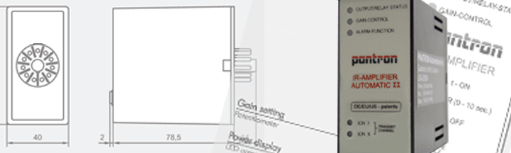
Check the silver tag on the back of the amplifier to determine the correct supply voltage for that model. Using a volt meter, test across pins 2 and 10 for the correct voltage reading. |
| Amplifier will not power ON. (Part 2) |
If the correct power is present on pins 2 and 10, remove the amplifier from the socket and inspect the sides for discoloration or bulging of the plastic housing. Is the amplifier hot or producing a strong odor? If so, the amplifier may be damaged due to voltage spike (ie: lightning) and should be replaced. |
| Output status light remains illuminated constantly. |
The photo eyes may not see each other. Check for obstructions between the photo eyes. Clean the face of each photo eye with a mild non-abrasive detergent. Align the photo eyes using the "string method" (shown below) of stretching a string or wire between the photo eyes so that the string passes by the eye in parallel. If both photo eyes are parallel to the string, the alignment should be correct. Check for cracks or deep scratches in the face of each photo eye. Water intrusion through a crack could damage the photo eye circuitry. If either photo eye appears damaged replace it immediately. |
| Amplifier diagnostics report "no signal." (via Output Status/No Signal LED) |
The photo eyes cannot see each other. Check for obstructions between the photo eyes. Clean the face of each photo eye with a mild non-abrasive detergent. Align the photo eyes using the "string method" (shown below) of stretching a string or wire between the photo eyes so that the string passes by the eye in parallel. If both photo eyes are parallel to the string, the alignment should be correct. Check for cracks or deep scratches in the face of the photo eye. Water intrusion through a crack could damage the photo eye circuitry. If either photo eye appears damaged replace it immediately. |
| Output Status LED intermittently flickers |
Since the problem is intermittent, it may be challenging to diagnose the problem. Clean the face of each photo eye with a mild non-abrasive detergent. Align the photo eyes using the "string method" (shown below) of stretching a string or wire between the photo eyes so that the string passes by the eye in parallel. If both photo eyes are parallel to the string, the alignment should be correct. Check for cracks or deep scratches in the face of the photo eye. Water intrusion through a crack could damage the photo eye circuitry.
|
| Output Status LED intermittently flickers. (Part 2) |
Look closely at the receiver photoeye while the problem is occuring. If the receiver is mounted in direct sunlight, this may cause intermittent false signals. Verify that pin 7 on the amplifier socket, also transmitter (black), shares a connection to Earth ground. If a higher transmit power is needed from the amplifier, connect a jumper wire between pin 7 and pin 11. This will increase the transmit level from "Low 1" to "Low 2." If either photo eye appears damaged replace it immediately.
|
| Output Status LED will not turn ON. |
The receiver photo eye may see infrared light from the transmitter through reflections, or due to incomplete blockage of the receiver by the object being detected. (creating a silhouette) The viewing angle of the receiver may need to be narrowed using a polarized filter or by creating a shield around the eye. |
| Output Status LED will not turn ON. (Part 2) |
If more than one set of photo eyes are in-use in the same area, verify that there is no "crosstalk" between the systems. If two sets of photo eyes must be used in close proximity, try alternating the side that the transmitter and receiver of the second set is mounted on. |
| Amplifier responds the opposite of its expected operation |
The problem may be the way that the output is wired. Pantron automatic amplifiers with transistor output may be wired for PNP or NPN. Verify that the correct wiring configuration is in place for the application. Pantron automatic amplifiers with relay outputs offer a normally open (NO) connection on pin 3 and a normally closed (NC) connection on pin 4. Verify that the correct wiring configuration is in place for the application. |